How to Connect Two Serial Devices to Ethernet
Plan a two-channel serial-to-Ethernet architecture, compare dual-port and single-port device servers, and select verified DTECH roles for RS232, RS485 and RS422 equipment.
Quick Answer: Use Two Defined Serial Channels, Not a Passive Split
To connect two serial devices to one Ethernet network, use a dual-port serial device server when both devices are near the same cabinet and each needs an independent serial channel. Configure the interface and framing for each channel, then assign the correct TCP, UDP or protocol-conversion role on the Ethernet side. The DTECH serial-to-Ethernet connectivity solution maps this architecture to verified product roles without treating two devices as one shared serial signal.
A dual-port device server consolidates hardware and one Ethernet uplink, but it does not merge two serial conversations. Each channel still requires the correct RS232 or RS485 wiring, baud rate, data bits, parity, stop bits, application protocol and network-session plan.
What Does a Dual-Port Serial Device Server Do?
A dual-port serial device server is a network edge device that connects two serial channels to an IP network through one Ethernet interface. The serial channels remain logically separate even though they share the same network appliance and Ethernet cable.
This is different from an electrical splitter. RS232 is normally a point-to-point electrical interface, while an RS485 bus has its own multidrop wiring rules. Joining two unrelated serial devices onto one conductor does not create two independent data paths. A device server instead receives bytes from each configured serial channel and transports them through the selected IP operating mode.
The transport choice matters. The IETF's TCP specification, RFC 9293, defines TCP as a connection-oriented byte-stream protocol. The original UDP specification, RFC 768, describes a datagram service with minimal protocol mechanism and without guaranteed delivery or duplicate protection. A project should therefore select TCP or UDP according to the host application, not simply because both options appear in a configuration menu.
How Should Two Serial Devices Connect Through One Ethernet Uplink?
Use a four-layer architecture and document every boundary:
- Serial device A and serial device B: Record each device's electrical interface, connector, pinout, baud rate, data bits, parity, stop bits and application protocol.
- Independent device-server channels: Configure channel 1 and channel 2 separately. Do not assume identical settings merely because both devices use RS485 or both use the same cabinet.
- Industrial Ethernet path: Assign IP addressing, network mode, destination address and port behavior. Coordinate firewall, VLAN, VPN and remote-access controls with the site network owner.
- Host or monitoring application: Confirm whether the host opens connections, listens for incoming sessions, receives UDP datagrams or expects explicit protocol conversion.
The DTECH serial-to-Ethernet solution presents this as field devices → serial channels → device server → Ethernet → SCADA or host. It is suitable for two nearby meters, controllers, instruments or other compatible serial devices that must reach an IP-based application.
When Is One Dual-Port Server Better Than Two Single-Port Servers?
Choose by physical architecture and operational ownership, not by hardware count alone.
| Selection dimension | One dual-port server | Two single-port servers | Better fit |
|---|---|---|---|
| Device location | Both devices are close to one cabinet or network drop | Devices are in separate cabinets or buildings | Follow the actual cable routes |
| Ethernet cabling | One shared uplink is preferred | Two independent uplinks are available or required | Match switch-port and redundancy plans |
| Power and maintenance | One power point and one device simplify the installation | Independent replacement and isolation boundaries matter | Follow the maintenance strategy |
| Serial interfaces | Both channels are supported by the same verified model | Devices require different unsupported interfaces or environmental ratings | Verify each channel, not just the product family |
| Failure domain | Both channels may be affected by one appliance outage | Each device must remain independent from the other server | Use the required availability boundary |
| Expansion | Two channels cover the documented scope | Future devices are physically distributed | Plan the next network edge, not only today's port count |
A dual-port server is usually the cleaner role when two compatible serial devices are colocated. Two single-port servers may be the safer architecture when the devices are far apart, belong to different systems, use different power or grounding domains, or require independent maintenance windows.
Which Network Mode Should Each Serial Channel Use?
How does TCP Server mode fit?
In TCP Server mode, the device server listens for an incoming TCP connection from a host application. This can suit a central application that knows the server's IP address and opens the session. Confirm how many connections the exact model and host software support; do not infer connection capacity from the words “TCP Server.”
When does TCP Client mode fit?
In TCP Client mode, the device server initiates a connection to a configured destination. This can be useful when the field edge should actively connect to a known host. The destination address, port, reconnect behavior and network policy must be documented before commissioning.
When is UDP appropriate?
UDP removes TCP connection setup and preserves datagram boundaries, but RFC 768 does not provide ordered, reliable delivery. Use it only when the application is designed for UDP behavior and can tolerate or detect loss, duplication or reordering at the system level.
When is Modbus conversion required?
Transparent transport and protocol conversion are different roles. If the host sends Modbus TCP while the field device uses Modbus RTU or ASCII, the selected model must explicitly support and be configured for that conversion. The Modbus Organization's Modbus Messaging on TCP/IP Implementation Guide separates Modbus client, server and gateway behavior and explains that Modbus communication over TCP requires managed TCP connections.
MQTT is another distinct application-layer option. The OASIS MQTT 5.0 standard defines MQTT as a client-server publish/subscribe messaging transport. A model listing MQTT should not be assumed to behave like a transparent virtual serial port; verify the payload and broker workflow.
Which Product Role Fits the Connection?
| Verified product role | Serial and network fit | Selection conditions | Product page |
|---|---|---|---|
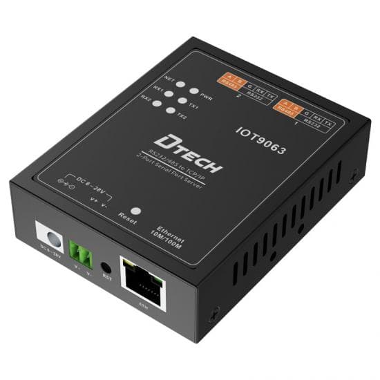
| Two independent RS232/RS485 channels | IOT9063 connects two configurable RS232 or RS485 channels to one 10/100M Ethernet port | 2400–115200 bps, TCP Server/Client, UDP Server/Client, HTTP and MQTT modes, Modbus TCP-to-RTU/ASCII conversion, DC 9–38V | IOT9063 dual-port serial device server |
| Multi-standard serial integration | IOT9031A supports RS232, half-duplex RS485 and full-duplex RS422 with 10/100M Ethernet | TCP/UDP server or client modes, documented Modbus RTU/TCP pass-through and DC 5V for the verified hardware version | IOT9031A three-in-one serial device server |
| One high-rate RS422/RS485 channel | IOT9031B connects one RS422/RS485 interface to 10/100M Ethernet | 300–921600 bps, TCP/UDP server or client modes and DC 9–40V | IOT9031B RS422/RS485 serial server |
The IOT9063 is the direct dual-channel role for two nearby RS232 or RS485 devices. The IOT9031A is a different role when interface flexibility across RS232, RS485 and RS422 is more important than a documented two-channel layout. The IOT9031B is appropriate when the requirement is one RS422/RS485 channel with its verified rate and power range.
How Do You Select and Configure the Server?
Step 1: Inventory both serial endpoints
Photograph the connector and record the terminal labels. Confirm RS232 versus two-wire RS485 versus four-wire RS422, plus signal ground, polarity and any termination or biasing instructions. Use the RS232, RS422 and RS485 comparison guide if the electrical layer is unclear.
Step 2: Record framing and protocol settings
For each device, record baud rate, data bits, parity and stop bits. Then identify whether the payload is proprietary, Modbus RTU, Modbus ASCII or another protocol. A transparent device server preserves the serial payload; it cannot repair incompatible device addresses or register maps.
Step 3: Draw the network sessions
Mark which endpoint initiates each connection, which IP address and port it uses, and whether the application expects one or multiple simultaneous sessions. Treat channel 1 and channel 2 as separate rows in the commissioning sheet.
Step 4: Verify power, environment and protection
Check the exact product page for DC input, temperature range, enclosure and documented protection. Do not copy a power range from another model in the same product family. If the serial cable crosses power systems or electrically noisy areas, complete a grounding, isolation and surge-risk review before installation.
Step 5: Commission one channel at a time
First confirm local serial communication and Ethernet reachability. Test channel 1 from the real host application, then channel 2, and finally test both under normal polling or message timing. Save the final device configuration, IP plan and cable drawing.
What Common Design Mistakes Cause Failures?
- Treating two ports as one combined stream: Each serial channel needs an independent mapping and host-side session plan.
- Selecting by connector shape: A terminal block does not prove whether the interface is RS232, RS485 or RS422.
- Mixing transparent transport with gateway conversion: Modbus TCP-to-RTU conversion is a configured protocol role, not an automatic property of Ethernet transport.
- Using UDP without application support: The application must be designed for datagram behavior and possible loss or reordering.
- Ignoring port conflicts: Document the TCP or UDP port used by each channel and confirm that firewalls and host software match it.
- Exposing the device directly to the public Internet: Put remote access behind the organization's approved network-security architecture rather than relying on a serial server alone.
- Copying settings between channels: Two similar devices can still use different addresses, parity or timing.
- Skipping configuration backup: Record the final settings so a replacement device can be commissioned predictably.
What Should Be Checked Before Installation?
- Interface, connector and pinout confirmed for both devices
- Baud rate, data bits, parity and stop bits recorded per channel
- Application protocol and device addresses documented
- Transparent transport versus protocol conversion decided
- TCP Server, TCP Client or UDP role drawn for each channel
- IP address, destination and network ports reserved
- Power input and operating environment verified on the exact model
- Grounding, isolation and surge conditions reviewed
- Firewall, VLAN, VPN and remote-access rules approved by the network owner
- Channel-by-channel commissioning and recovery plan prepared
- Product manual and final configuration backup available
FAQ
What is a dual-port serial device server?
A dual-port serial device server connects two serial channels to an IP network through one Ethernet device. The channels share the Ethernet uplink but keep their own serial and network configuration. It is not a passive electrical splitter.
Can two serial devices share one Ethernet connection?
Yes, when the device server provides two documented serial channels. Each device still needs compatible wiring, framing and protocol settings. The host application must also know how it connects to each channel.
When should I use two single-port serial servers instead?
Use separate servers when the devices are in different cabinets or locations, require different power or protection boundaries, or must remain independently replaceable. Two servers can also match a network design that requires separate Ethernet failure domains.
Does serial-to-Ethernet conversion change the protocol?
Transparent serial transport does not automatically change the application payload. Protocol conversion, such as Modbus TCP to Modbus RTU or ASCII, must be explicitly supported and configured. Verify the exact model and host workflow before deployment.
Can one dual-port server mix RS232 and RS485?
Only if the product documentation permits each channel to use the required interface. The verified IOT9063 data specifies two independent channels configurable for RS232 or RS485. Confirm the terminal assignment for each channel in the model-matched manual.
What should be recorded before selecting a serial device server?
Record the interface and connector for each device, baud rate, data bits, parity, stop bits, protocol, network mode and IP addressing. Also document power input, operating environment, grounding and any isolation or surge requirement.
Authoritative Sources
- RFC 9293 — Transmission Control Protocol, RFC Editor / IETF Standards Track.
- RFC 768 — User Datagram Protocol, RFC Editor.
- Modbus Specifications and Implementation Guides, Modbus Organization.
- MQTT Version 5.0, OASIS Standard.
Ask DTECH to Review the Two-Channel Architecture
Send the two device interfaces, serial settings, protocol, network modes, power input, cabinet layout and host-software behavior to the engineering team. Review the complete serial-to-Ethernet connectivity solution, compare the verified product roles above, or ask an engineer to review the project.