How Do You Replace an RS485 Cable with a Wireless Serial Link?
Design a wireless RS485 link by matching serial interfaces, topology and RF conditions, then commission the real route before replacing the cable.
Quick Answer: Replace the Cable Path, Not the Serial Design
To replace an RS485 cable with a wireless serial link, install a matched wireless endpoint at each side, keep the required serial framing and device addresses, and commission the radio path under real site conditions. The wireless hop replaces the transmission medium; it does not automatically correct RS485 wiring, convert Modbus registers or remove response-time constraints. Select the USB, RS232 or RS485 variant required at each endpoint, then verify topology, antenna position, regional radio rules and application timing before retiring the cable. The DTECH remote wireless serial communication solution organizes these decisions around a LoRa/TPUNB wireless endpoint and optional local RS485 branch equipment.
What Does Replacing an RS485 Cable Actually Mean?
An RS485 cable carries differential signals between local transceivers. A wireless pair receives serial bytes, transports them by radio and presents them at the remote side. The field protocol may remain, but the physical path and timing behavior have changed.
For Modbus RTU and other request-response systems, framing, device addresses, polling intervals and timeouts still belong to the application. Do not describe a transparent radio link as a protocol gateway unless its documentation explicitly provides conversion.
LoRa and LoRaWAN are also different entities. Semtech's LoRa and LoRaWAN technical overview describes LoRa as a physical-layer radio technology and LoRaWAN as a network protocol and architecture. A dedicated LoRa-based serial link is therefore not automatically a LoRaWAN gateway or cloud deployment.
When Is a Wireless RS485 Link a Practical Choice?
A wireless hop is worth evaluating when a new cable route would cross a road, yard, moving structure, leased area or finished building; when trenching would interrupt operations; or when remote equipment must be added without rebuilding the whole communication route. It can also provide a defined bridge between two local serial segments that are physically difficult to join.
Retain a wired path when the radio system cannot demonstrate the required timing, antenna placement is impractical, radio use is restricted, or a safety function has not been designed and validated for wireless communication. Treat availability, latency and recovery as measured requirements.
Which Wireless Architecture Should You Use?
Use point-to-point for one defined cable replacement
Point-to-point is the clearest architecture when one local serial segment must communicate with one remote segment. Each side uses a compatible wireless endpoint, and both endpoints are configured for the same radio and serial operating conditions. Start with this architecture when the objective is a direct replacement for one physical route.
Use point-to-multipoint only when polling and addressing allow it
Point-to-multipoint can connect one supervisory location to several remote endpoints when the application distinguishes devices and the radio system supports that topology. Account for shared airtime, polling, reply timing and an unavailable endpoint.
Keep local RS485 branches separate from the radio topology
One wireless endpoint may connect to a local RS485 trunk or an active hub, but that wired segment remains an RS485 design problem. Avoid a passive star at the radio interface. Where field cables must split into defined routes, use a verified active branch role and follow the RS485 star topology and hub guide.
How Do Wired and Wireless Serial Paths Compare?
| Engineering condition | Existing or new RS485 cable | Wireless serial hop | Decision evidence |
|---|---|---|---|
| Physical route | Requires a continuous cable, installation access and termination plan | Requires a usable RF path and suitable antenna positions | Site survey and route drawings |
| Serial compatibility | Both ends must match RS485 wiring and framing | Each wireless endpoint must match its local interface and framing | Endpoint manuals and captured settings |
| Timing | Propagation is usually small relative to application timing | Radio transport can add variable delay and recovery behavior | Measured request-response tests |
| Interference | Susceptible to electrical noise, grounding and cable-layout problems | Susceptible to RF obstruction, interference and antenna-placement problems | Tests during normal site operation |
| Topology | Controlled bus preferred; active hubs create defined branches | Point-to-point or documented multipoint roles | Product topology documentation |
| Regulation | Electrical and installation rules apply | Electrical rules plus regional radio requirements apply | Local regulatory review |
| Maintenance | Inspect cable, terminals, shielding and termination | Inspect power, serial wiring, radio configuration and antennas | Commissioning record and spares plan |
The table is a selection framework, not a claim that one medium is universally more reliable. The installed design and its operating conditions determine the result.
Which Product Role Fits the Wireless RS485 Design?
| Verified product role | Confirmed use in the architecture | Selection conditions | Product page |
|---|---|---|---|
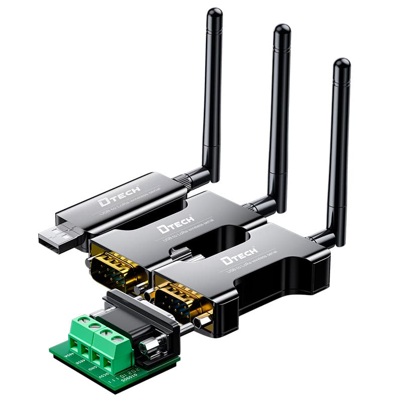
| Wireless serial endpoints | TPUNB Series provides separate USB, RS232 and RS485 variants using LoRa/TPUNB, with point-to-point and multipoint roles and no cellular data card dependency | Choose the interface variant at each location; confirm model, regional use, power, radio settings and site performance before purchase | TPUNB wireless serial transceivers |
| Two protected local branches | DT-9022 distributes an RS422/RS485 connection across two active branches | Use only where two defined local field routes are needed; verified range is 300–115200 bps with DC 9–40V input | DT-9022 two-port RS485 hub |
| Four isolated local branches | IOT9024I distributes an upstream RS232/RS485 connection to four independently isolated RS485 groups | Use where four local groups and per-port isolation are required; verify device loading, 300–921600 bps range and DC 9–38V input | IOT9024I four-port RS485 isolation hub |
The TPUNB Series is the primary wireless role. DT-9022 and IOT9024I are optional local distribution roles; they do not create the radio link or solve every RS485 loading condition.
How Should the Connection Architecture Be Designed?
Use a four-stage path: local equipment or host → matched wireless endpoint → commissioned RF link → remote endpoint and local serial segment. Add an active RS485 branch role only where multiple local cable routes require it. Document power, grounding, antenna position and serial references.
The LoRa Alliance's regional parameters guidance shows why frequency plans, data rates, transmit constraints and other radio parameters vary by region. Even when a product uses a dedicated LoRa-based serial mode rather than LoRaWAN, the project still needs a region-appropriate model and a local compliance review. Do not copy radio settings from another country or infer approval from the word “LoRa.”
How Do You Select and Commission the Link Step by Step?
Step 1: Capture the existing serial link
Record interface type, connector and pinout, two-wire or four-wire arrangement, baud rate, data bits, parity, stop bits, protocol, device addresses, polling interval and timeout. Capture a known-good transaction if the existing cable still works. This becomes the acceptance reference for the wireless path.
Step 2: Choose each endpoint interface independently
Select the local variant required at each side. An RS485 field bus may need an RS485 wireless endpoint, while a maintenance computer may need a separate USB variant. Do not assume that USB, RS232 and RS485 are simultaneous ports on one product when the verified series data describes separate variants.
Step 3: Map the radio path and regulatory region
Mark endpoint height, obstacles, terrain, antenna routes and nearby radio systems. Confirm the intended country before selection. The US FCC Part 15 rules and European ETSI short-range-device framework are official references; neither proves approval for a particular product or project.
Step 4: Separate radio topology from local RS485 topology
Define which wireless endpoints communicate with each other, then draw the wired devices connected to each endpoint. Use a controlled RS485 bus where possible. If the site needs separate field routes, document why a two- or four-branch active hub is required and verify its serial, isolation, power and loading conditions.
Step 5: Bench-test the complete application
Connect the intended host, both endpoints and a real field device. Verify framing, addressing, direction control, polling, timeout and power-cycle recovery. A terminal test proves byte transfer; an application test evaluates protocol behavior.
Step 6: Commission the installed route with margin
Test during representative site activity and weather where relevant. Record transactions, retries, response time and recovery at the intended load. Accept the link only after the real route meets the project criteria.
What Common Mistakes Should Be Avoided?
- Treating LoRa as a distance guarantee: usable range depends on the exact radio, settings, antennas, obstructions, interference and legal constraints.
- Calling every LoRa link LoRaWAN: a LoRa physical layer does not establish LoRaWAN protocol support.
- Mixing endpoint interfaces: RS232, RS485 and USB require the correct local variant and wiring.
- Ignoring protocol timing: a wireless path can alter response behavior even when the payload remains transparent.
- Creating a passive RS485 star: the radio hop does not remove wired-bus topology rules at either endpoint.
- Selecting from a bench test alone: a short indoor test does not represent the installed RF path or normal plant activity.
- Assuming regulatory approval: verify the exact model, region and installation requirements through appropriate documentation and authorities.
What Should Be Checked Before Purchase?
- Existing serial interface, framing, protocol, node addresses and timeouts recorded
- USB, RS232 or RS485 variant selected separately for each endpoint
- Point-to-point or multipoint radio topology documented
- Local RS485 trunk or active branch plan documented
- Site obstructions, endpoint positions and antenna routes reviewed
- Country or regulatory region confirmed for the exact model
- Power supplies, grounding and enclosures specified at both locations
- Bench and installed-route acceptance tests defined
- Failure recovery, maintenance access and spare-unit plan agreed
- Model review based on current verified product documentation completed
FAQ
Can a wireless serial link directly replace an RS485 cable?
It can replace the transmission path when both wireless endpoints use the correct serial-interface variants and the application can tolerate the measured wireless behavior. Serial framing, device addresses, timing and the field protocol still need to match at both ends.
Does a wireless RS485 link change Modbus RTU data?
A transparent wireless serial link should carry serial payloads rather than translate them, but that behavior must be confirmed for the exact product and mode. Modbus RTU addresses, baud rate, parity, stop bits and response timing remain application requirements.
Is a LoRa wireless serial link the same as LoRaWAN?
No. LoRa describes a radio modulation technology, while LoRaWAN is a network protocol and architecture built on LoRa. A dedicated LoRa-based serial link should not be described as a LoRaWAN deployment unless the product documentation explicitly supports LoRaWAN.
Which interface variant is needed at each wireless endpoint?
Choose the variant that matches the local equipment interface at that endpoint, such as RS485 for a two-wire field bus, RS232 for a point-to-point serial port or USB for a compatible host. Do not assume one enclosure provides all interfaces when the product family uses separate variants.
Can one wireless endpoint connect several RS485 devices?
It may serve a documented local RS485 bus or a defined hub-based branch architecture when addressing, loading, timing and topology are compatible. The wireless topology and the local wired topology are separate design decisions and must both be commissioned.
How far will a wireless RS485 link work?
No universal distance can be guaranteed from the words LoRa or wireless RS485 alone. Antenna placement, obstructions, interference, radio settings, regional limits, endpoint height and the exact product determine the usable link, so test the actual route with margin.
Authoritative Sources
- LoRaWAN for Developers and Regional Parameters, LoRa Alliance.
- LoRa and LoRaWAN: A Technical Overview, Semtech.
- 47 CFR Part 15 — Radio Frequency Devices, US Federal Communications Commission rules published in the Electronic Code of Federal Regulations.
- Short Range Devices, European Telecommunications Standards Institute.
- RS-422 and RS-485 Standards Overview and System Configurations, Texas Instruments.
Ask DTECH to Review the Wireless Serial Architecture
Send the two endpoint interfaces, protocol settings, existing cable route, proposed endpoint positions, obstruction notes, topology, country of use, power availability and local RS485 branch count to the engineering team. Review the complete wireless serial communication solution, compare the verified product roles above, or request a project-specific model review.