When Should You Use an RS232 Isolator?
Use an RS232 isolator when compatible point-to-point devices need a defined electrical boundary, then verify pinout, signals, baud rate, distance and power.
Quick Answer: Add Isolation at an Electrical Boundary, Not by Default
Use an RS232 isolator when two RS232 devices must exchange data but should not share a direct electrical reference because of ground-potential differences, recurring port damage, electrostatic discharge exposure or conducted interference. Place the isolator inline between the host and field device, then verify connector gender, DTE/DCE pinout, supported signals, baud rate, cable length and power method. An isolator preserves compatible RS232 data; it does not convert RS232 to RS485, correct crossed pins or repair mismatched serial settings. The DTECH serial interface conversion and isolation solution maps this requirement to verified point-to-point product roles.
What Does an RS232 Isolator Do?
An RS232 isolator creates a documented electrical barrier inside an otherwise point-to-point RS232 connection. Data crosses the barrier through the product's isolation circuitry, while the connected equipment is not tied through the same direct conductive signal path. This can reduce the effect of ground-loop current and help limit the transfer of specified electrical disturbances between ports.
RS232 remains a single-ended interface on both sides of the isolator. Texas Instruments' summary of interface standards describes TIA/EIA-232-F as an unbalanced, point-to-point interface, while Analog Devices' RS232 fundamentals explains the DTE/DCE relationship and the data and control signals commonly found on the connector. The isolator does not change that architecture into a multidrop bus.
Isolation is also different from surge or ESD protection. Isolation describes the barrier between electrical domains; ESD and surge specifications describe defined transient tests or protection functions. Compare each rating separately on the exact product page and do not treat one number as proof of every protection requirement.
When Is an RS232 Isolator the Right Solution?
Choose an RS232 isolation role when the project has a clear electrical reason for separating two compatible RS232 endpoints.
When the devices use different grounding domains
Two devices powered from different cabinets, supplies or building circuits may not sit at the same ground potential. A direct signal-ground connection can then carry unwanted current or move the RS232 reference outside the conditions expected by the equipment. Texas Instruments' Digital Isolator Design Guide shows an isolated RS232 interface and explains the separate signal and power domains used in an isolated design.
When the serial route is exposed to electrical disturbance
RS232 cables near relays, contactors, drives or frequently connected service equipment can be exposed to transient or static-discharge events. A model with documented isolation and ESD data can add a defined protection layer, but it does not replace cabinet grounding, cable routing, bonding or installation-level surge protection.
When unexplained failures follow the cable or connected equipment
Repeated port damage, communication loss when another machine starts, or errors that disappear when a laptop runs on battery are reasons to investigate the electrical reference. Measure and diagnose the installation before selecting a device; those symptoms can also come from wiring, power quality, connector damage or software timing.
When the requirement is same-interface protection
Use an RS232-to-RS232 isolator when both endpoints already use compatible RS232 signaling and the requirement is separation, not conversion. If the field device actually uses RS485, RS422, TTL or Ethernet, choose the correct converter or serial server instead.
When Is an RS232 Isolator Not Enough?
An isolator is not a universal serial troubleshooting tool. It will not correct any of the following conditions:
- A DTE-to-DTE connection that requires a null-modem wiring arrangement
- Reversed TXD and RXD pins or an incompatible proprietary DB9 pinout
- Required RTS, CTS, DTR, DSR, DCD or RI control lines that the isolator does not pass
- Different baud rate, data bits, parity, stop bits or application protocol
- A cable route longer than the model's documented RS232 distance
- A device that needs RS232-to-RS485, RS422, TTL or Ethernet conversion
- A safety-isolation requirement that has not been reviewed against the complete equipment standard
The control-line question is especially important. A compact three-wire isolator may carry TXD, RXD and signal ground only. Confirm every signal used by the application before ordering; connector shape alone does not prove functional compatibility.
How Should the Connection Architecture Be Designed?
Use a simple documented path: RS232 host → short verified cable → RS232 isolator → short verified cable → RS232 field device. Put the isolation barrier where the two electrical domains meet, not randomly in the cable route. Keep each side within the selected model's distance and pinout limits.
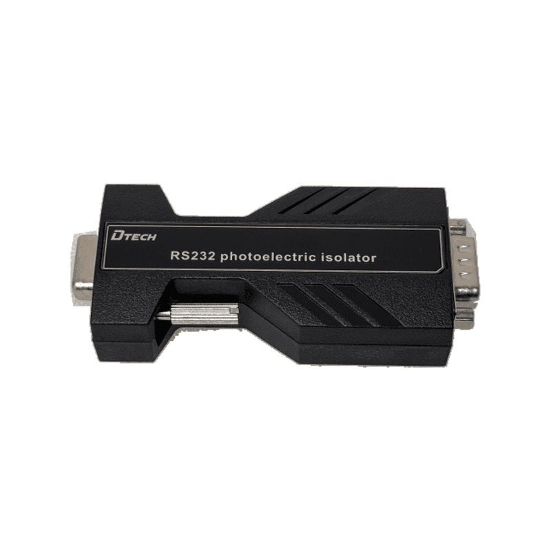
Before installation, draw the connector gender and pin assignment at all four interfaces: host, first cable end, isolator input/output and field device. State whether the endpoints are DTE or DCE, whether a straight-through or null-modem path is required, and which control lines are active. Then record the serial framing and application behavior independently of the electrical design.
How Do the Verified Product Roles Compare?
| Product role | Verified communication data | Verified isolation and protection data | Selection condition | Product page |
|---|---|---|---|---|
| Primary inline industrial RS232 isolation | IOT9011; DB9 male/female; transparent full duplex; 300–115200 bps; up to 15 m on each side | Up to 3500Vrms isolation; ±15 kV air and ±8 kV contact ESD data; serial-port powered | Use when the documented rate, distance, connector and environmental range fit the project | IOT9011 RS232 isolator |
| Passive high-rate legacy role | DT-9011; TXD/RXD/GND; DB9 female/male; source-specified 300–912600 bps; 5 m | Source specifies 5000V isolation, 15 kV ESD and 600 W surge protection | Use only when its exact pinout, short distance and source-specified rate are required and verified | DT-9011 passive isolator |
| Self-powered transparent inline role | DTIB-0708; DB9 male/female; transparent full duplex; 300–115200 bps; 15 m at each end | Up to 3500Vrms isolation; ±15 kV air and ±8 kV contact ESD data; no external supply | Use as an inline alternative when its model-specific mechanical and electrical data match | DTIB-0708 RS232 isolator |
Do not rank the isolation figures by number alone. The DT-9011 source uses “5000V,” while the other pages specify “Vrms”; test method, duration, insulation classification and the applicable equipment standard determine what a rating means. Select against the complete product documentation and project requirement.
Texas Instruments' isolated RS232 reference design also demonstrates that isolated signal transfer and isolated power are separate design functions. A finished inline product may draw usable energy from serial-port signals, but that power method still needs to work with the actual host port.
How Do You Select and Commission an RS232 Isolator?
Step 1: Confirm that both endpoints are RS232
Record each equipment model, connector, DTE/DCE role and pinout. Do not assume a DB9 connector is standard RS232 or that every vendor uses the same pins. Use the RS232, RS422 and RS485 comparison guide if the field interface is uncertain.
Step 2: Inventory every required signal
List TXD, RXD and signal ground, then identify any hardware-flow-control or modem-control lines. Match that list to the isolator's documented pins. If the application requires a signal the product does not pass, select a different architecture.
Step 3: Map the electrical boundary
Identify power supplies, protective earth connections, cabinet boundaries and nearby switching equipment. Place the isolator between the two domains that need separation. Do not use multiple isolation devices without a clear electrical diagram.
Step 4: Match rate, distance and power
Compare the configured baud rate, cable length on each side, connector gender, temperature range and power method with the exact model. A port-powered device must be tested with the real controller, computer or USB-to-serial adapter because available serial-port energy can vary.
Step 5: Test function before the installed route
Bench-test the host, isolator and field device at the production serial settings. Confirm bidirectional data and any required control behavior. Then install the real cables and repeat the application test while surrounding equipment operates normally.
Step 6: Record the final configuration
Save the pinout, cable type, model, direction, baud rate, framing and test result. Label the isolation boundary in the cabinet or equipment drawing so maintenance teams do not bypass it later.
What Common Selection Mistakes Should Be Avoided?
- Selecting by DB9 gender only: gender does not identify DTE/DCE wiring or required control signals.
- Assuming every pin is isolated: verify the documented signal list; compact models may support only the data path.
- Confusing isolation with interface conversion: an RS232 isolator keeps RS232 on both sides.
- Comparing voltage labels without test context: units and test methods must be comparable before ranking products.
- Ignoring port-powered compatibility: the real host must provide the operating conditions expected by the device.
- Extending the total cable beyond the specification: treat per-side distance and total route as separate checks.
- Expecting isolation to fix software settings: framing and protocol must still match.
- Skipping the installed-environment test: bench success does not reproduce cabinet grounding or switching events.
What Should Be Checked Before Purchase?
- Both endpoints confirmed as compatible RS232 interfaces
- DTE/DCE role, connector gender and pinout documented
- Required data and control signals matched to the isolator
- Baud rate and framing within the exact model specification
- Cable length verified on both sides of the isolation boundary
- Port-powered or external-power method confirmed with the real host
- Isolation, ESD and surge requirements reviewed separately
- Grounding domains and cable route shown on the connection drawing
- Bench and installed-site commissioning plan prepared
- Product page and source-matched specification retained for procurement
FAQ
What is an RS232 isolator?
An RS232 isolator passes compatible serial data across an electrical isolation barrier between two RS232 devices. It is used to separate signal-reference domains and can include documented ESD or surge protection, depending on the exact model.
Does an RS232 isolator convert RS232 to RS485?
No. RS232 remains on both sides of the isolator. Use a verified RS232-to-RS485 converter when the field equipment uses differential RS485 signaling.
Can an RS232 isolator fix a ground loop?
It can break the direct signal path that contributes to ground-loop current when installed at the correct boundary. The complete grounding, power and safety design must still be reviewed because other conductive paths may remain.
Does every RS232 isolator pass hardware flow control?
No. Some inline models document only TXD, RXD and ground-related connections. Confirm RTS, CTS, DTR, DSR, DCD and RI requirements against the product pinout before purchase.
Does a port-powered isolator work with every USB-to-RS232 adapter?
Not necessarily. Serial-port voltage and available energy can vary by implementation. Test the exact adapter, isolator, baud rate and cable route before standardizing the assembly.
Where should an RS232 isolator be installed?
Install it where the two electrical domains meet, with each cable side kept within the model specification. The connection drawing should show host and device pinouts, cable type and the isolation boundary.
Authoritative Sources
- AN-216 — Summary of Well Known Interface Standards, Texas Instruments.
- Fundamentals of RS-232 Serial Communications, Analog Devices.
- Digital Isolator Design Guide, Texas Instruments.
- TIDA-01230 — Isolated RS-232 With Integrated Signal and Power Reference Design, Texas Instruments.
Ask DTECH to Review the RS232 Isolation Boundary
Send the two equipment models, DTE/DCE pinouts, required signals, baud rate, cable lengths, power sources, grounding relationship and protection requirement to the engineering team. Review the complete serial interface conversion and isolation solution, compare the verified roles above, or request an RS232 isolation review.