Passive vs Isolated RS232 to RS485 Converter: Which One?
Compare passive and isolated RS232-to-RS485 converter roles, then select by host power, grounding boundary, protection, wiring mode and verified distance.
Quick Answer: Choose Isolation When Electrical Risk Is Part of the Link
Use a passive RS232-to-RS485 converter only when the RS232 port can reliably power the converter, the link is a straightforward two-wire half-duplex connection, and both ends share a controlled electrical environment. Choose an isolated, externally powered converter when the cable crosses grounding domains, runs near motors or switching equipment, requires verified surge or ESD protection, or must support RS422 as well as RS485. Isolation does not fix wrong serial settings, but it separates signal references and reduces the risk that ground-potential differences or transients pass directly between connected systems. The DTECH serial interface conversion and isolation solution maps those conditions to verified passive and isolated product roles.
What Is the Difference Between Passive and Isolated Converters?
A passive RS232-to-RS485 converter derives operating energy from the RS232 side instead of requiring a routine external DC supply. It changes the electrical interface so an RS232 host can communicate with compatible RS485 equipment. Available port power and signal conditions must be verified on the actual host.
An isolated converter adds an electrical isolation barrier between the host side and the field bus, and normally uses an external power supply. Data crosses the barrier, while direct current flow between the two signal-reference domains is blocked within the device's documented isolation design. Isolation and surge protection are related but different specifications; neither should be inferred unless the exact product documentation states it.
Texas Instruments' RS232-to-RS485 reference design illustrates that conversion requires an RS232 transceiver, RS485 transceiver and direction-control function, with isolation and isolated power added for the protected design. This is why converter selection must cover power, duplex mode, grounding and protection—not just connector shape.
When Is a Passive RS232-to-RS485 Converter Appropriate?
Choose a passive converter when all of these conditions are true:
- The host exposes a compatible RS232 port and can supply the operating energy expected by the converter.
- The field connection is a documented two-wire, half-duplex RS485 link.
- The route stays within a controlled cabinet, bench or common grounding environment.
- The project does not require a stated galvanic-isolation rating.
- The required baud rate, node loading, cable length and connector pinout match the exact model documentation.
A passive converter is not automatically the correct low-cost choice for every installation. A modern USB-to-serial adapter, low-voltage UART implementation or nonstandard port may not provide the same usable handshake-line energy as a traditional RS232 port. Confirm operation with the real host and full cable route before standardizing the design.
The DTECH DT-9000 passive RS232-to-RS485 converter is the direct passive role in this comparison. Its verified data specifies 300–115200 bps, asynchronous half-duplex operation, less than 1200 metres on the RS485 side and an RS232-side distance within 15 metres. Those are model limits, not a promise that every installation will reach the maximum distance.
When Should You Choose an Isolated Converter?
Choose an isolated, externally powered converter when the cost of communication failure or electrical coupling is material. Typical triggers include different buildings or power systems, long field cables, motor drives, variable-frequency drives, relays, contactors, outdoor routes, exposed equipment, repeated unexplained port damage or a formal isolation requirement.
Analog Devices' AN-960 RS485/RS422 implementation guide explains that long links can create ground-potential differences and ground currents, while motors and switching equipment can introduce ground noise. The guide presents galvanic isolation as a way to allow information flow without the same direct ground-current path when earth potentials cannot be kept within the transceiver's common-mode range.
Texas Instruments' RS422 and RS485 standards overview likewise describes balanced transmission, termination and system configurations, and shows isolated arrangements for controlling ground loops between remote stations. These sources support a design decision based on electrical boundaries—not a blanket statement that isolation makes every network immune to wiring or protocol errors.
How Do Passive and Isolated Options Compare?
| Selection condition | Passive converter | Isolated, externally powered converter | Engineering decision |
|---|---|---|---|
| Power | Draws operating energy from the RS232 side | Requires the model's documented DC input | Verify the real host port or cabinet supply |
| Electrical separation | No stated galvanic barrier unless documented | Provides a specified isolation barrier | Use isolation where grounding domains or protection requirements justify it |
| Field environment | Controlled, low-risk routes | Industrial noise, long routes or different power systems | Base the decision on the cable path and connected equipment |
| Serial modes | Commonly two-wire half-duplex RS485 | May support RS485 half-duplex and RS422 full-duplex | Match the exact device wiring mode |
| Protection | Varies by model; do not assume | ESD and surge data may be explicitly specified | Compare each protection rating separately |
| Installation | Compact and no routine supply wiring | Requires power, mounting and grounding plan | Include commissioning and replacement requirements |
| Failure consequence | Suitable where a simple link can be tested and replaced easily | Better role where downtime or equipment exposure is material | Document risk before selecting by price |
Which Product Role Fits the Project?
| Verified product role | Confirmed fit | Selection conditions | Product page |
|---|---|---|---|
| Compact passive RS232-to-RS485 conversion | DT-9000 connects an RS232 host to half-duplex RS485 equipment | 300–115200 bps; RS485 distance less than 1200 m; RS232 side within 15 m; no claimed isolation barrier | DT-9000 passive converter |
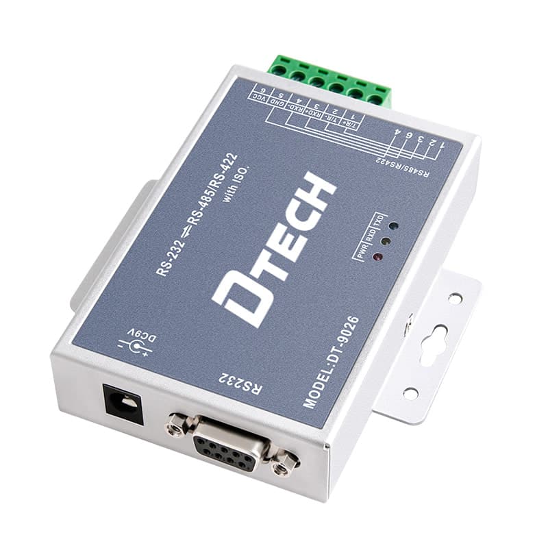
| Isolated RS232-to-RS485/RS422 conversion | DT-9026 adds 2500Vrms isolation and protected interfaces | RS485 half-duplex or RS422 full-duplex; up to 115.2 Kbps; up to 1200 m; DC 9–24V; documented ESD and surge protection | DT-9026 isolated converter |
| Isolated role for a source-specified extended route | DT-9028 adds 2500Vrms isolation with RS485 or RS422 conversion | Up to 115.2 Kbps; source-specified reach up to 5,000 m dependent on baud rate; −40°C to 85°C documented operating range | DT-9028 industrial isolated converter |
The DT-9000 is the simple passive role, not the default for noisy or cross-building routes. The DT-9026 is the documented isolated role for a protected link up to its verified 1200-metre condition. The DT-9028 is a separate extended-distance role; its maximum must be treated as conditional on baud rate, cable and installation quality rather than as a universal result.
How Should the Connection Architecture Be Designed?
Use a five-part architecture: RS232 host → converter → isolated or non-isolated boundary → RS485/RS422 cable → field equipment. The converter changes the physical signaling, but the application payload remains serial data. Modbus RTU addresses, proprietary message formats and device timing do not change merely because the electrical interface changes.
For RS485, confirm whether the equipment uses two-wire half-duplex operation. For RS422 or four-wire operation, confirm separate transmit and receive pairs at both endpoints. National Instruments' RS485 two-wire and four-wire guidance distinguishes half-duplex and full-duplex wiring and notes that transmission lines require appropriate termination to control reflections.
How Do You Select the Converter Step by Step?
Step 1: Identify both electrical interfaces
Record the host connector, pinout and RS232 control lines. At the field endpoint, confirm RS485 versus RS422, two-wire versus four-wire operation, terminal naming and signal reference. Do not select from the words “serial port” alone.
Step 2: Record the serial framing and protocol
Write down baud rate, data bits, parity, stop bits, device address and application protocol. The converter cannot reconcile mismatched framing or Modbus register definitions. Use the RS232, RS422 and RS485 comparison guide when the electrical layer is still uncertain.
Step 3: Map the grounding and cable route
Mark cabinet boundaries, buildings, power supplies, protective earth connections, motor or drive cables and outdoor exposure. If the endpoints can sit at different ground potentials, treat isolation as an engineering requirement to evaluate rather than an optional accessory.
Step 4: Match protection and power
Verify isolation voltage, ESD, surge, power input and temperature on the exact model page. An isolation number does not replace an installation-level surge-protection, grounding or safety review. Ensure the specified DC supply is available and appropriate.
Step 5: Commission at the real baud rate
Test locally, then test over the installed cable with the intended node count and normal equipment operating. Check polarity, termination, biasing and direction timing. Save the wiring diagram and verified settings for replacement and maintenance.
What Common Selection Mistakes Should Be Avoided?
- Assuming passive means universally compatible: RS232 port-power availability varies by host implementation.
- Treating isolation as protocol conversion: Isolation separates electrical domains; it does not translate Modbus addresses or data formats.
- Selecting by maximum distance alone: Baud rate, cable, termination, loading and noise determine the achievable route.
- Confusing RS485 and RS422 wiring: Two-wire half-duplex and four-wire full-duplex roles require different terminals and data-direction behavior.
- Assuming isolation includes every protection function: Compare isolation, ESD and surge specifications as separate fields.
- Ignoring the RS232-side limit: A long RS485 specification does not make the host-side RS232 cable equally long.
- Testing only on a workbench: A clean short cable does not reproduce the grounding and interference conditions of the installed route.
What Should Be Checked Before Purchase?
- Host RS232 connector, pinout and usable port power confirmed
- RS485 or RS422 field interface and wire mode confirmed
- Baud rate, framing, protocol and node count recorded
- Cable length and route mapped against power and grounding domains
- Passive versus isolated boundary decision documented
- Exact isolation, ESD, surge, power and temperature specifications verified
- Termination, biasing and shield plan reviewed
- Commissioning test and configuration record prepared
- Product page, model-matched manual and inquiry package retained
FAQ
Does every RS232-to-RS485 connection need isolation?
No. A short link inside a controlled cabinet with compatible grounding may work with a verified passive converter. Isolation becomes the stronger choice when the cable crosses electrical domains, operates around meaningful noise or transients, or carries a protection requirement.
Can a passive RS232-to-RS485 converter work with any serial port?
Not necessarily. Passive converters depend on the electrical behavior and available energy of the host RS232 port. Test the exact computer, controller or adapter rather than assuming every DB9 or USB-serial implementation behaves identically.
Does an isolated converter fix RS485 communication errors?
It can address one class of electrical risk, such as ground-potential differences and coupled transients. It cannot fix reversed polarity, wrong baud rate, incorrect termination, duplicate device addresses or incompatible protocol settings.
Is surge protection the same as galvanic isolation?
No. Isolation defines an electrical barrier between domains, while surge protection describes how an interface handles specified transient energy. A product may provide both, one or neither, so verify each documented rating separately.
Should I choose RS485 or RS422 output?
Choose the interface required by the field equipment. Two-wire RS485 is commonly half duplex, while RS422 commonly uses separate transmit and receive pairs for full-duplex or simplex arrangements. Confirm the exact endpoint pinout and operating mode.
How far can an RS232-to-RS485 converter transmit?
Use the exact model specification as an upper conditional limit, not a guaranteed project result. Cable type, baud rate, termination, node loading, grounding and interference affect the practical distance, so validate the installed route.
Authoritative Sources
- TIDA-060008 — Reference Design for Converting RS-232 Signaling to RS-485 Signaling, Texas Instruments.
- AN-960 — RS-485/RS-422 Circuit Implementation Guide, Analog Devices.
- RS-422 and RS-485 Standards Overview and System Configurations, Texas Instruments.
- RS-485 Pins for 2- and 4-Wire Transmission, National Instruments.
Ask DTECH to Review the Electrical Boundary
Send the host pinout, field interface, cable length, baud rate, grounding domains, nearby equipment, protection requirement and available DC supply to the engineering team. Review the complete serial interface conversion and isolation solution, compare the verified product roles above, or request a model review.