Why RS485 Communication Fails: 12 Common Causes and Practical Troubleshooting Steps
Diagnose RS485 faults systematically by checking polarity, serial settings, topology, termination, grounding, cable quality, interference and protocol timing.
RS485 is widely used in industrial automation, energy monitoring, building control, access control, HVAC systems, and data acquisition because it supports differential signaling, multidrop networks, and longer cable distances than RS232.
However, RS485 communication problems are common during installation.
Typical symptoms include intermittent data loss, CRC errors, devices going offline, communication working only at low baud rates, or the network operating normally until additional devices are connected.
Most failures are not caused by the communication protocol alone. They are usually related to wiring, topology, termination, grounding, configuration, electrical noise, or equipment selection.
Quick Answer
When RS485 communication fails, first verify A/B polarity, baud rate, parity, device addresses, two-wire or four-wire mode, and power supply. Next, inspect bus topology, termination resistors, biasing, grounding, shielding, cable length, and electrical noise. Test the network in small sections before replacing equipment.
Understand the RS485 Layer First
RS485 defines an electrical communication method. It does not define the application protocol.
An RS485 network may carry:
- Modbus RTU
- BACnet MS/TP
- Profibus-related communication
- Proprietary binary commands
- ASCII commands
- Metering protocols
This means that correct RS485 wiring does not guarantee successful communication. The devices must also use compatible protocols, data formats, addresses, and timing.
Common RS485 Failure Symptoms
The symptom often provides a useful clue.
| Symptom | Likely Areas to Check |
|---|---|
| No device responds | Polarity, baud rate, wiring mode, power, master configuration |
| Some devices respond | Address conflict, topology, cable branch, load limit |
| Communication is intermittent | Termination, noise, grounding, loose terminals |
| Works at low baud rate only | Cable quality, distance, reflections, capacitance |
| Works when one device is disconnected | Address conflict, excessive load, faulty transceiver |
| CRC errors increase near motors | EMI, shielding, grounding, isolation |
| Communication stops after several hours | Power instability, software timing, overheating |
| Works on a test bench but not on site | Ground potential, cable routing, surge, interference |
1. Reversed A and B Wires
Reversed polarity is one of the most common causes of a completely silent RS485 network.
The challenge is that manufacturers do not always label differential lines consistently. Labels may include:
- A and B
- D+ and D-
- 485+ and 485-
- TX+ and TX-
- Non-inverting and inverting
Some manufacturers use A for the non-inverting line, while others use the opposite convention.
Troubleshooting Action
Check the pin definition in the manuals of both devices. Do not rely only on wire color or terminal lettering.
If communication does not work and all other parameters appear correct, temporarily swap the two signal wires at one end and test again.
Record the final wiring definition in the installation document.
2. Incorrect Two-Wire or Four-Wire Configuration
RS485 can operate in:
- Two-wire half-duplex mode
- Four-wire full-duplex mode
A two-wire device uses one differential pair for both transmission and reception. A four-wire device uses separate transmit and receive pairs.
Connecting a two-wire master directly to a four-wire slave without the correct wiring or converter configuration will prevent communication.
Troubleshooting Action
Confirm whether every device uses:
- RS485 two-wire
- RS485 four-wire
- RS422 four-wire
For four-wire connections, confirm that the transmitter of one device connects to the receiver of the other device.
3. Mismatched Baud Rate, Parity, Data Bits, or Stop Bits
All devices on the same serial communication segment must use compatible serial settings.
Common formats include:
- 9600, 8, N, 1
- 19200, 8, E, 1
- 115200, 8, N, 1
A mismatch in only one parameter can cause unreadable data or no response.
Troubleshooting Action
Create a communication parameter table containing:
- Device name
- Device address
- Baud rate
- Data bits
- Parity
- Stop bits
- Protocol
Do not assume factory-default settings are identical across different brands.
4. Duplicate Device Addresses
In a multidrop network, each slave device normally requires a unique address.
If two devices use the same Modbus slave ID, both may respond to the same request. The overlapping responses can produce CRC errors, corrupted frames, or unstable communication.
Troubleshooting Action
Disconnect all but one slave and test devices individually.
Verify and record each address before reconnecting the complete bus.
For larger installations, apply address labels to the physical devices and cables.
5. Incorrect Bus Topology
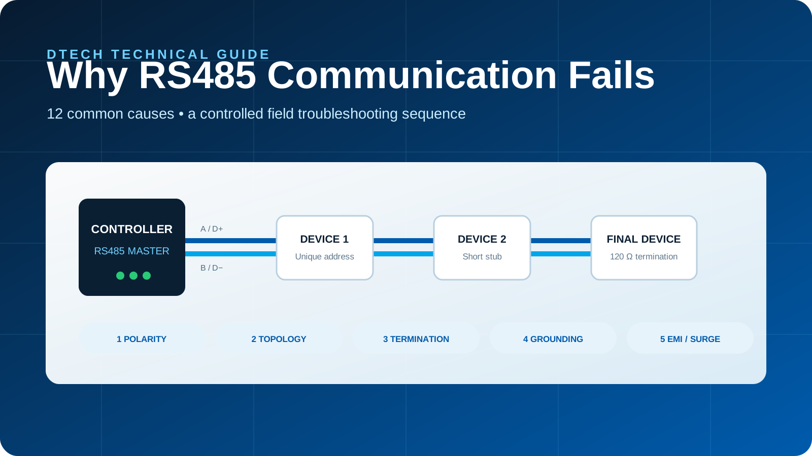
RS485 works best with a daisy-chain bus topology.
Common problematic layouts include:
- Star wiring
- Long branch lines
- Multiple uncontrolled junctions
- Ring connections
- Random parallel branches
Long stubs create signal reflections, especially at higher baud rates.
Recommended Topology
Use one main trunk cable and connect devices along the trunk with short branch lengths.
The ideal design is:
Master — Device 1 — Device 2 — Device 3 — Final Device
Avoid routing a separate long cable from a central point to every device unless the system has been specifically engineered for that topology.
6. Missing or Incorrect Termination Resistors
Termination resistors reduce signal reflections by matching the cable impedance.
In a conventional RS485 bus, termination is generally installed at the two physical ends of the main trunk.
A common nominal value is approximately 120 ohms, but the correct value should match the cable and equipment design.
Common Mistakes
- No termination at either end
- Termination on every device
- Three or more terminations
- Termination installed on branch lines
- Incorrect resistor values
- Built-in termination enabled without being documented
Too many termination resistors increase the electrical load and reduce signal amplitude.
Troubleshooting Action
Power off the bus and measure resistance between the two signal lines.
Two 120-ohm termination resistors in parallel normally produce a reading near 60 ohms, although connected equipment and bias circuits may affect the measurement.
Confirm the actual circuit rather than relying only on the meter reading.
7. Missing or Excessive Biasing
When no driver is actively transmitting, an RS485 bus can enter an undefined state.
Bias resistors maintain a known idle voltage and help prevent random transitions from being interpreted as data.
However, excessive biasing from multiple devices can overload the bus.
Troubleshooting Action
Identify which device provides fail-safe biasing.
Normally, biasing should be controlled at one appropriate location rather than enabled independently on every device.
Check whether bias resistors are built into:
- PLC communication modules
- Serial converters
- Repeaters
- Gateways
- Termination boards
8. Ground-Potential Differences
RS485 uses differential signaling, but the transceiver still has a limited common-mode voltage range.
When devices are powered from different panels, buildings, or grounding systems, the voltage difference between grounds can become excessive.
This may cause:
- Intermittent communication
- Damaged transceivers
- Communication failure during machine operation
- Failures after lightning or surge events
Troubleshooting Action
Measure the voltage difference between device grounds.
Where significant ground differences or strong electrical interference exist, consider:
- Isolated RS485 converters
- Isolated repeaters
- Isolated power supplies
- Fiber-optic transmission
- Improved grounding design
Isolation is particularly important in energy, industrial automation, outdoor equipment, and long-distance installations.
9. Poor Cable Selection or Shielding
RS485 should use a twisted-pair cable with suitable impedance and consistent construction.
Problems may occur when installers use:
- Untwisted alarm cable
- Random multi-core cable
- Different cable types in one bus
- Damaged cable
- Poor-quality terminal connections
- Shield connected incorrectly
- Signal cable routed with high-voltage power cables
Troubleshooting Action
Check:
- Cable type
- Twisted-pair consistency
- Shield continuity
- Connector quality
- Terminal tightness
- Cable damage
- Routing distance from motors and power cables
The shield connection method depends on the grounding design. Avoid connecting the shield in a way that creates unintended ground-loop current.
10. Excessive Distance, Baud Rate, or Device Load
RS485 distance and data rate are related.
Higher baud rates generally reduce the practical communication distance. Cable capacitance, topology, transceiver characteristics, termination, and environmental noise also affect performance.
The theoretical maximum in a product brochure should not be treated as a guaranteed field result.
Troubleshooting Action
Test the following:
- Reduce the baud rate.
- Disconnect some devices.
- Shorten the cable temporarily.
- Divide the network with an RS485 repeater.
- Test each cable segment individually.
If the network becomes stable after reducing speed or load, the physical bus design requires improvement.
11. Electrical Noise, Surge, and ESD
Variable-frequency drives, motors, contactors, relays, welding equipment, switching power supplies, and high-current cables can generate interference.
Noise may enter through:
- Signal lines
- Power inputs
- Ground connections
- Cable shields
- Nearby electromagnetic fields
Troubleshooting Action
Observe whether errors occur when specific machinery starts or stops.
Improve:
- Cable separation
- Shielding
- Grounding
- Surge protection
- Power filtering
- Electrical isolation
For harsh installations, use industrial communication devices with appropriate ESD, surge, and isolation protection.
12. Software Timing or Protocol Problems
The electrical layer may be correct while the application still fails.
Possible causes include:
- Incorrect Modbus function code
- Wrong register address
- Incorrect byte order
- Insufficient response timeout
- Polling interval too short
- Master sending a new request before the previous response is complete
- Broadcast requests used incorrectly
- Device requiring a silent interval between frames
- Serial-to-Ethernet packet timing configuration
Troubleshooting Action
Capture the communication data using:
- Serial monitoring software
- USB-to-RS485 adapter
- Protocol analyzer
- Oscilloscope
- Logic analyzer
- Serial device server diagnostic log
Compare the actual request and response frames with the device protocol manual.
A Step-by-Step RS485 Troubleshooting Procedure
Randomly changing several parameters at the same time makes diagnosis difficult.
Use a controlled sequence.
Step 1: Simplify the Network
Disconnect all slave devices except one.
Use a short cable and place the master and slave near each other.
This creates a known baseline.
Step 2: Confirm Power and Interfaces
Verify:
- Device power
- RS485 interface selection
- Two-wire or four-wire mode
- Terminal definition
- Communication indicator status
Step 3: Confirm Communication Parameters
Match:
- Baud rate
- Data bits
- Parity
- Stop bits
- Slave address
- Protocol mode
Step 4: Verify Polarity
Confirm A/B or D+/D- wiring from the product manuals.
Test by swapping the pair if the labeling convention is uncertain.
Step 5: Test the Protocol
Send one known valid command.
For Modbus RTU, verify:
- Slave address
- Function code
- Register address
- Quantity
- CRC
Step 6: Add Devices One at a Time
Reconnect each slave individually.
After adding each device, confirm that the complete network remains stable.
This helps identify:
- Duplicate addresses
- Faulty devices
- Excessive loading
- Problematic cable branches
Step 7: Restore the Full Cable Route
Test the actual cable and final installation.
Monitor communication while motors, pumps, relays, and other nearby equipment operate.
Step 8: Check Signal Quality
An oscilloscope can reveal:
- Reflections
- Low differential voltage
- Excessive ringing
- Common-mode problems
- Noise spikes
- Slow signal edges
This is useful when basic wiring checks do not identify the problem.
When Should You Use an Isolated RS485 Converter?
Consider isolation when:
- Devices use different power systems.
- Equipment is installed in different electrical cabinets.
- The cable passes outdoors.
- Ground voltage differences are present.
- The installation includes motors or variable-frequency drives.
- Transceivers have previously failed.
- The RS485 network connects power or energy equipment.
- Communication becomes unstable during equipment switching.
Isolation does not correct protocol settings or poor topology, but it can protect equipment and reduce problems caused by ground differences and interference.
When Should You Add an RS485 Repeater?
A repeater may help when:
- The cable is too long.
- Too many devices are connected.
- The network must be divided into several electrical segments.
- A branch cannot be avoided.
- Signal quality is poor at the far end.
- Electrical isolation is needed between sections.
A repeater regenerates the electrical signal. It does not normally convert the application protocol.
For networks that need protected branch distribution, review the DTECH DT-9022 Industrial 2-Port RS485 Hub. For four independently isolated branches, see the DTECH IOT9024I 4-Port RS485 Isolation Hub. Product selection must still be based on the verified interface, distance, device count and electrical environment of the project.
Factory Testing and Pre-Shipment Verification
For project orders, the supplier should receive the customer requirements before shipment whenever possible.
Useful information includes:
- Number of devices
- Communication protocol
- Serial settings
- Cable length
- Network topology
- Power input
- Installation environment
- Isolation requirement
- Connector type
- Destination market
A practical shipment inspection can include:
- Serial loopback testing
- RS485 transmit and receive testing
- High and low baud-rate verification
- Power-cycle testing
- Terminal inspection
- Isolation verification for isolated models
- Surge-protection component inspection where applicable
- Product label verification
- Accessory and power adapter verification
- Packaging inspection
Testing should reflect the actual product specification and customer application rather than relying only on a power-on test.
Installation Preparation Checklist
Before commissioning, prepare:
- Final wiring diagram
- Device address list
- Communication parameter table
- Cable and shield specification
- Termination locations
- Biasing location
- Grounding method
- Power supply plan
- Test command or software
- Spare converter or adapter
- Troubleshooting record
Frequently Asked Questions
Should RS485 have a termination resistor?
Longer or higher-speed RS485 buses normally require termination at the two physical ends of the main trunk. Short, low-speed networks may operate without termination, but the final design should be based on signal quality and equipment requirements.
Why does RS485 work when only one device is connected?
Possible causes include duplicate addresses, excessive bus loading, incorrect topology, too many termination resistors, or a faulty device.
Can I connect all RS485 devices in a star topology?
A star topology may work at short distances and low speeds, but it increases the risk of reflections. A daisy-chain bus with short stubs is generally more reliable.
Should RS485 ground wires be connected?
A reference conductor may be required, depending on the device design and grounding system. However, careless grounding can create ground loops. Follow the equipment manuals and consider isolation where ground differences exist.
Why does communication fail only when a motor starts?
The motor, drive, contactor, or associated power wiring may be introducing electrical noise or ground disturbance. Check cable routing, shielding, grounding, power quality, surge protection, and isolation.
Can a USB-to-RS485 adapter be used for troubleshooting?
Yes. It can help verify serial parameters and test individual devices. Make sure the adapter supports the required baud rate, operating system, isolation level, and RS485 wiring mode.
Conclusion
RS485 communication problems should be diagnosed systematically.
Start with polarity, wiring mode, serial settings, device addresses, and power. Then evaluate topology, termination, biasing, cable quality, grounding, electrical noise, distance, and protocol timing.
Do not replace equipment until the fault has been isolated. However, when the root cause involves ground differences, harsh electrical environments, excessive distance, or unstable signal quality, an industrial isolated converter or repeater may be the correct long-term solution.
Need Help Reviewing an RS485 Application?
Send DTECH your wiring diagram, baud rate, number of devices, cable distance, protocol, installation environment, and current fault symptoms.
Our team can help identify whether the project requires an RS485 converter, isolated converter, repeater, serial device server, or wireless serial solution.