RS485 Star Topology: When to Use a Multi-Branch Hub
Compare RS485 daisy-chain and star wiring, learn when an active hub is needed, and select the right two-, four- or eight-branch product role.
Quick Answer
For a conventional RS485 network, start with a controlled daisy-chain trunk and keep device stubs short. A passive star made by joining several long cable branches at one terminal block can create multiple reflection paths, unclear termination points and difficult fault isolation. If the plant layout genuinely requires separate branches, use an active RS485 hub to divide the upstream connection into defined field segments.
The correct hub is selected by upstream interface, branch count, baud rate, isolation, protection, power input, device loading and cable environment. DTECH's RS485 network segmentation solution maps these conditions to verified two-, four- and eight-branch product roles.
What Is an RS485 Star Topology?
An RS485 star topology is a physical layout in which one central junction connects three or more cable branches. The central point may be a passive terminal block or an active hub. These two architectures are electrically different and should not be treated as interchangeable.
In a passive star, the wires are simply joined. Every branch remains part of one transmission line, so each open or terminated cable path can affect signal reflections. In an active multi-branch network, a hub receives the upstream serial signal and drives separate output branches according to the product's documented architecture.
This distinction matters because RS485 defines the electrical signaling layer. It does not correct application settings, device addresses or protocol data. A hub cannot fix mismatched baud rate, parity, Modbus addresses or register definitions.
Why Daisy Chain Is the Starting Point
Texas Instruments' official RS-422 and RS-485 system configuration guide describes daisy chaining as a widely used configuration because the stations are attached successively and the main bus behaves more like one transmission line. Its RS-485 Design Guide also recommends short stubs and termination matched to the cable's characteristic impedance to reduce reflections.
A practical daisy-chain network normally has:
- one documented trunk route;
- short connections from the trunk to each device;
- consistent A/B polarity and serial settings;
- termination placed according to the real cable endpoints and equipment instructions;
- biasing defined at the system level rather than added randomly at multiple devices.
Daisy chain is not automatically correct merely because the cable follows a line. Long side branches, undocumented junction boxes or several enabled termination resistors can still create an unstable network. Use the RS485 troubleshooting guide to verify wiring and settings before redesigning the topology.
Daisy Chain vs Passive Star vs Active Hub
| Architecture | Electrical behavior | Best fit | Main engineering risk |
|---|---|---|---|
| Daisy-chain trunk | One controlled bus with short device stubs | Equipment located along one route | Long stubs, wrong endpoint termination or inconsistent polarity |
| Passive star junction | Several cable branches electrically joined at one point | Only when the complete signal-integrity design has been validated | Multiple reflection paths and unclear termination boundaries |
| Active RS485 hub | Upstream serial link redistributed across active branches | Production cells, cabinets or device groups that require separate cable routes | Selecting the wrong interface, rate, isolation or branch capacity |
| Serial repeater | One serial path regenerated or extended | Distance extension or segment separation along a route | Assuming every repeater provides multiple branches or isolation |
| Serial device server | Serial data transported through an Ethernet network | Remote IP access or centralized Ethernet monitoring | Confusing transparent transport with electrical branch distribution |
An active hub is not a universal cure. It is the correct product role when the required physical connection architecture cannot be implemented as one controlled trunk or when the project needs verified branch isolation or fault containment.
When an Active RS485 Hub Is the Better Design
1. The cable routes leave one cabinet in different directions
A production controller may need to communicate with machines in separate cells. Combining all routes at a passive terminal block creates a star. An active hub provides defined output branches so each route can be documented and commissioned as a segment.
2. Different device groups need electrical separation
Equipment in separate cabinets or powered areas can experience different grounding and interference conditions. A hub with verified per-port or system isolation can be appropriate when the installation risk requires electrical separation. Isolation ratings must be checked on the exact model; never assume that every product called a hub is isolated.
3. A branch fault should not stop the other branches
In a shared passive segment, a wiring fault can affect the wider bus. When branch-level fault containment is a requirement, select a product whose verified data explicitly describes short-circuit, open-circuit or independent-branch behavior.
4. The network needs staged commissioning
Multiple defined branches let the installer test polarity, serial settings, termination and device response one segment at a time. This does not remove the need for protocol diagnostics, but it makes the physical network easier to document.
5. The upstream interface and field interface differ
Some hubs accept an RS232 or RS485 main connection and distribute RS485 branches; others use an RS422/RS485 main bus. The source interface must be confirmed before selecting the branch count.
Recommended DTECH Multi-Branch Architecture
The DTECH RS485 network segmentation solution uses a four-layer connection path:
- Upstream controller or gateway: Record whether the source interface is RS232 or RS485 and confirm baud rate, parity, data bits and protocol behavior.
- Main serial link: Document two-wire or four-wire wiring, cable type, grounding, shielding and the intended termination arrangement.
- DTECH RS485 hub: Select the active distribution, isolation and protection role that matches the branch plan.
- Field segments: Treat each machine group, meter group or control area as a documented branch with its own cable route and endpoint checks.
This architecture is suitable for factory automation, distributed metering, building control and access systems when the physical site requires multiple defined serial branches. It is not a substitute for protocol conversion or Ethernet transport.
Which DTECH RS485 Hub Role Fits the Project?
| Product role | Verified interfaces and branch role | Verified selection conditions | Product page |
|---|---|---|---|
| Two-branch isolated distribution | DT-9022 supports an RS422/RS485 main bus and two RS485 branches | 300–115200 bps, 2500Vrms isolation and DC 9–40V input | DT-9022 two-port RS485 hub |
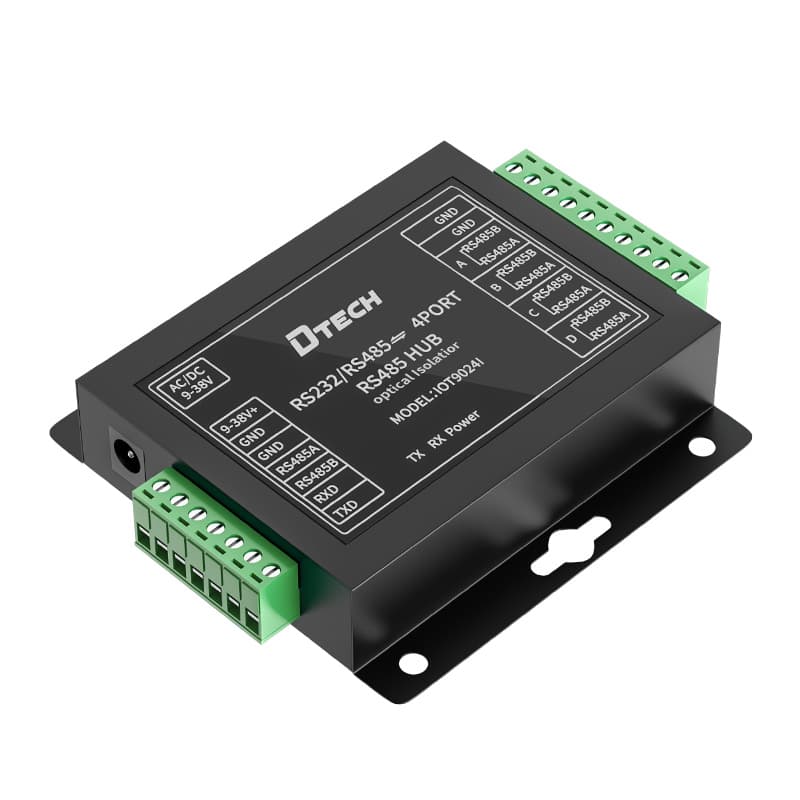
| Four-branch per-port isolation | IOT9024I accepts RS232/RS485 and provides four independently operating RS485 groups | 300–921600 bps, 2500Vrms isolation per port, up to 32 devices per group and DC 9–38V input | IOT9024I four-port RS485 isolation hub |
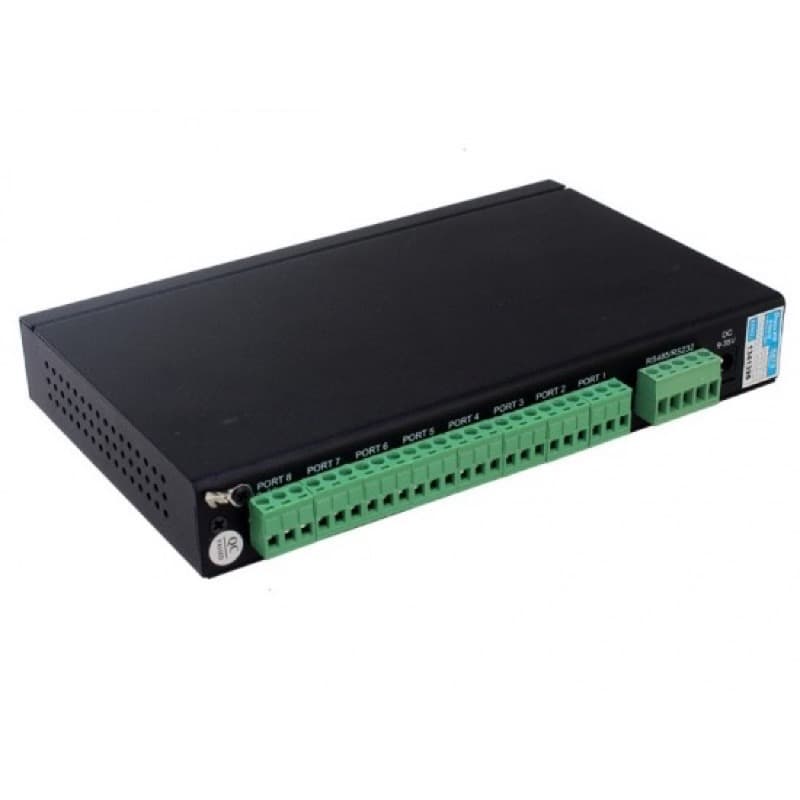
| Eight-branch expansion | DT-9028I distributes one RS232/RS485 main connection across eight RS485 branches | Adaptive branch communication up to 250 Kbps, documented branch fault protection and DC 9–40V input | DT-9028I eight-port RS485 hub |
These rows describe product roles, not a universal model ranking. The fastest or largest hub is not automatically the best choice. A two-branch isolated design may be more appropriate than an eight-branch unit when the project needs only two field routes and a specific RS422/RS485 main interface.
RS485 Hub Selection Steps
Step 1: Draw the physical cable routes
Mark the controller, cabinets, machine groups, meters and field endpoints. Count real routes rather than counting devices. Twenty devices along two routes may need two branches, while eight devices in eight remote cabinets may need more.
Step 2: Confirm the upstream interface
Record whether the controller or gateway supplies RS232, two-wire RS485, four-wire RS485 or RS422. Do not select a hub from the branch labels alone.
Step 3: Record serial and protocol settings
Document baud rate, parity, data bits, stop bits, response timing and protocol. If Modbus RTU is used, record addresses and expected polling behavior. All devices on a transparent serial path must remain compatible.
Step 4: Define isolation and protection requirements
Identify separate power systems, ground-potential risk, motor drives, switching equipment, outdoor routes and surge exposure. Match these conditions to verified isolation, ESD and surge specifications on the exact product page.
Step 5: Check loading and branch capacity
Use the transceiver and product documentation rather than assuming that every RS485 node represents the same electrical load. Confirm the product's stated capacity for each branch and leave practical expansion margin.
Step 6: Design termination per active segment
Termination must match the active cable topology and characteristic impedance. Do not enable a termination resistor at every device, and do not assume that every hub branch has the same internal termination arrangement. Follow the hub and endpoint documentation.
Step 7: Commission one branch at a time
Verify polarity, idle voltage, settings and device response on the main connection, then add one branch at a time. Record the final cable route, device order, termination state and test result for future maintenance.
Common RS485 Star-Topology Mistakes
- Treating a terminal block as a hub: A passive junction does not regenerate or isolate the signal.
- Buying by port count only: Upstream interface, rate, isolation, protection and power matter as much as branch count.
- Using a hub to solve protocol errors: Physical distribution cannot correct wrong addresses, parity or register definitions.
- Enabling termination everywhere: Extra termination can overload the driver and distort the network.
- Assuming isolation from the product category: Verify the isolation rating and whether it applies per port or to the complete device.
- Mixing A/B naming without testing polarity: Vendor labels are not always interpreted consistently across equipment.
- Skipping branch documentation: An active hub improves structure only when cable routes and endpoints remain controlled.
- Ignoring the upstream segment: A correctly designed branch cannot compensate for a faulty controller-to-hub connection.
Pre-Installation Checklist
- Upstream interface and connector confirmed
- Two-wire or four-wire mode recorded
- Baud rate, parity, data bits and stop bits recorded
- Protocol and device addresses confirmed
- Physical branch count based on cable routes
- Device loading checked for each branch
- Isolation and surge environment reviewed
- Power input available at the hub location
- Cable type, shield and grounding plan documented
- Termination and biasing plan documented per active segment
- One-branch-at-a-time commissioning procedure prepared
- Product manuals and wiring diagrams available to the installer
Frequently Asked Questions
Can RS485 use a star topology?
A passive star can create long stubs and multiple reflection paths, so a controlled daisy-chain bus is normally preferred. When the physical site requires separate branches, an active RS485 hub can create defined segments instead of a passive wire split.
What does an RS485 hub do?
An RS485 hub receives the upstream serial signal and distributes it across multiple active branches. Depending on the verified model, it may also provide isolation, surge or ESD protection, branch fault protection, interface conversion or a defined branch capacity.
Does every RS485 branch need termination?
Termination must match the actual active topology, cable characteristic impedance and equipment instructions. Do not copy a two-resistor trunk rule blindly onto every hub branch; confirm the hub manual and the electrical endpoints of each segment.
Is an RS485 hub the same as a repeater?
The roles overlap but are not identical. A repeater normally regenerates or extends one serial path, while a hub distributes an upstream link into multiple branches. Product naming varies, so compare the documented architecture and specifications.
Can an RS485 hub fix wrong baud rate or Modbus settings?
No. A hub cannot correct mismatched baud rate, parity, addresses or register definitions. Verify the serial and application-protocol settings before changing the physical topology.
How do I choose between a two-, four- and eight-port RS485 hub?
Start with the number of physical field segments, then confirm the upstream interface, branch baud rate, isolation and protection requirements, power input, device loading, cable routes and environmental conditions against the verified product data.
Ask DTECH to Review Your RS485 Branch Plan
Send DTECH a simple drawing showing the upstream controller, interface, baud rate, device count, cable routes, cabinet boundaries, power input and electrical environment. We can help identify whether the project needs the two-branch DT-9022, four-branch isolated IOT9024I, eight-branch DT-9028I or a different serial communication architecture.
Review the complete RS485 network segmentation solution or send the project requirements to a DTECH engineer.